Can you see me now?

This is part three of my smart light adventure: be sure to check out part one and part two.

My (endearingly) luddite kids are going to hate this one even more than the last. Now my lights don’t just listen to my voice, they turn on automatically when they see me show up. Well, sometimes they do. Time will tell if this first attempt at motion sensing will be awesome or annoying, but this Raspberry Pi business just keeps getting cooler and cooler.

There are of course a ton of potential motion-triggered scenarios; I focused my effort on two that I encounter pretty much every day:

  1. Our ancient dog often needs to get up overnight to go to the bathroom (it’s like having a baby but you have to go outside in the rain). It’d be really nice if the lights came on just a little so that I could see where I was going, then turned themselves off after I was back into bed.
  2. When I get up on Fall or Winter mornings, it’s almost always still dark — a small but notable daily gut punch that comes with living at 48°N. It’d be nice if the lights just came on automatically so I could pretend it was sunny.

The “Easy” Way (Ring and IFTTT)

As it turns out, we already have Ring cameras in many of our rooms — the obvious approach was just to tap into those motion signals to trigger the lights. Unfortunately, Ring doesn’t have an open developer program. There are some reverse-engineered libraries out there (e.g., for Python and Typescript) and they seem fine, but you’re going to start using third party stuff anyways, the private integration at IFTTT.com is way more convenient. “If This Then That” has been around for years, a nerd’s paradise that enables connections between all sorts of Internet services and resources. IFTTT “applets” connect “IF THIS” conditions (“I get an email” or “the stock market closes” or “Camila Cabello posts to Instagram”) with “THEN THAT” actions (“Play a chime on my Alexa” or “Text me the closing price of MSFT” or “Open the Instagram app on my Roku TV”).

Since Ring is connected to IFTTT, The “IF THIS” part of my scenario is no problem:

  1. Sign up for the IFTTT service. You can create up to three applets for free; beyond that (and for more complex logic) you need to cough up for a “Pro” subscription.
  2. On the IFTTT Ring page, click “Connect” to start an authentication sequence where you grant IFTTT access to your Ring account.
  3. Create a new applet, click the IF THIS “Add” button, and search for and choose Ring.
  4. Click “New Motion Detected” and then pick the correct device in the dropdown.

Halfway there. But the “THEN THAT” side is a little more complicated. Remember the whole discussion last time about getting a message from the Internet back to our home controller app? Same issue here, but now we can just drop a message into the very same queue we created for Alexa. Given the ubiquity of Amazon Web Services, I assumed there would already be a “THEN THAT” action to handle this. Cue the Samuel L. Jackson voiceover — no dice. Building one was pretty easy, though.

Using the same AWS account we created to hold the SQS queue last time, I created an AWS Lambda function using the “microservice-http-endpoint” blueprint. I let it create a new Role for the function, and added an SQS SendMessage policy to that role the same way we did for the Alexa role. I chose “Create an API” with the “HTTP” option and set Security to “Open” (note this does mean there is a URL on the internet that can turn my lights on and off; good luck finding it).

Once this was all created, I added some code almost identical to what we used in Alexa; you can find it on github in zwave/lambda/index.js. After deploying the function, I copied the endpoint URL shown in the console and went back to IFTTT, chose the “webhook” action and pasted in the URL adding query string parameters for “screenName” and “settingName”.

Magic! Now whenever my Ring camera detects motion, it tells IFTTT, which calls the Lambda function, which drops a message into the SQS queue, which is picked up by the server in my house, which applies the requested setting to the lights. A little Rube Goldberg, but it works pretty well. Being able to re-use the queue is particularly satisfying; the home control server didn’t have to change at all for this to work.

An entertaining exercise, and it would certainly be nice to reuse motion sensors already in place. But there are a few ways in which this solution just doesn’t meet the brief:

  1. There are a million handoffs; in practice it can take up to ten seconds or even more for messages to make it to the queue. This delay is unacceptable; lights need to come on right away to be useful.
  2. Without adding the pro subscription, there’s no reasonable way to to turn the lights OFF once motion stops. We could handle this within the Lambda function (wait on a timer and then add another message to the queue), but it still wouldn’t be perfect, because there is no “motion ended” trigger from the Ring (we’ll talk more about optimizing this delay later on).
  3. Ring cameras are just expensive, and I don’t have them at all the places I’d eventually like to monitor.
  4. Even if I managed to work around these … I just can’t swallow adding more external services into my lighting solution. Remember, I started this whole journey because I got screwed by a random cloud service. There must be a better way!

The “Awesome” Way (PIR + Pi)

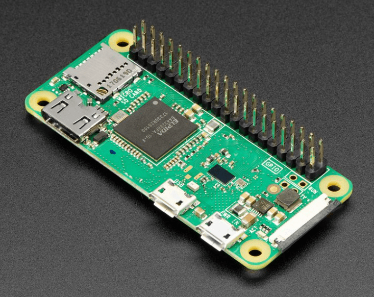
Of course there is. The Raspberry Pi already running our Z-Wave gateway is also an excellent device integration platform. It also turns out that reliable motion sensors are super-cheap. Seems like there’s a solution in there, and a fun one at that. Let’s play and see what happens!

First, the hardware. The most common way for electronics to detect human motion is with Passive Infrared Sensors (PIRs). These sensors respond to the heat signals emitted by all warm-blooded creatures and don’t rely on visible light, so they work reliably in the dark as well. Plus they’re very cheap; I picked up a five-pack of Stemedu HC-SR501 sensors for under $11 at Amazon, just nuts. These sensors add a bunch of logic beyond simple detection; specs are basically:

  • 5V input voltage required
  • 3.3V TTL output (low on quiet, high when motion detected)
  • Variable sensitivity from about 3 – 7 meters.
  • Variable delay (amount of time the signal will remain high) from about 3 seconds – 5 minutes.
  • Single or Repeatable Trigger Mode. In “Single” mode, motion detection starts the delay timer. TTL output remains high through the delay period and then drops low regardless of what happens during the delay. In “Repeatable” mode, the delay restarts with each motion event, only going low when there has been no motion for a full delay period. This second option basically keeps the signal high as long as there is activity within range of the sensor.

This is a pretty ideal match for the Pi, which has a number of General Purpose I/O (GPIO) pins made to directly accept TTL signals, and provides 5V power for attached devices. Repeatable Trigger Mode is also perfect for our “nightlight” use case — we can activate the lights when the sensor goes HIGH and turn them off when the value goes LOW — i.e., after I’ve left the room and gone back to bed.

Wiring it Up

The coolest thing about the Pi platform is its standard set of input and output pins, ready-made for attaching external devices (switches, sensors, lights, cameras, displays, etc.) with minimal additional circuitry. It’s perfect for somebody like me who kind of gets the basics of electronics, but quickly gets lost in the details of really making components work without frying themselves. Which is not to say that you can’t brick your Pi as well; it’s just a little harder.

Because the pins are (mostly) consistent across all Pi models, it’s created a huge market for daughter boards (amusingly also called “Hardware Attached on Top” or HATs) that easily extend the Pi for particular purposes. The RaZberry that was the star of the first Z-Wave post is one of these, which is awesome, except for one thing — the board covers up physical pins 2 and 4, which provide the five volts I need for the PIR sensor. There are many ways to work around this, but I chose to just use the 5V that standard USB ports provide instead. I started with a simple USB power cable and just hacked off the barrel plug to get access to the positive and negative wires. That left just the sensor’s TTL pin to attach. I used a utility knife to cut a little access port in the top of the Pi case, and connected that to physical pin 15 on the Pi (the RaZberry only covers physical pins 1-10, leaving a bunch open for other purposes).

The Pi model 3B has a header block attached, so instead of soldering anything, I was able to use Dupont-style crimp pins to make the connections. This was my first time using these, and it took a few tries to get comfortable with the process, but I am a convert! Basically you squish a male or female pin so that it grabs the insulation and contacts the wire, then insert it into a connector housing. The connectors can hold many wires in a row — a single female pin connected to the Pi, while three female pins in a triple housing attached to the sensor. I used this crimping tool and found this tutorial invaluable. The only trick is that the SB-28B crimper comes with the jaw plates installed the inverse of the tool in the video; if you pay attention it’s fine, but you can swap the jaws if you like, which also makes it a little easier for righties to use them.

Because the sensor outputs TTL voltage, this setup didn’t require any additional circuitry. Typically with an input sensor like this you’d want to add a pull-down resistor to ensure that voltage “float” doesn’t cause spurious events when the sensor is low. But the Pi comes through for us again — each GPIO pin has internal pull-up and pull-down resistors that can be enabled in software. These resistors, their values and default states cause significant confusion in the Pi community; I found this article to be definitive and super-helpful in figuring out what was up.

Accessing the GPIO Pins in Code

With the sensor powered up and connected, it was time to start coding. Pi4J is the “obvious choice” for Pi GPIO access from my old friend Java, so I dug in there. Pi4J is split into two very distinct major version branches: 1.x is built on the WiringPi library and supports Java 8 (except the very last release, 1.4). Version 2.x replaces WiringPi with PIGPIO and is a significant refactor that requires Java 11. I chose to go with Pi4J v1.3 in order to preserve Java 8 compatibility, and because 2.0 still seems a bit like a work in progress.

It’s worth understanding WiringPi a bit. It is installed by default on the Raspberry Pi OS and includes:

  • gpio, a command-line utility that runs setuid as root and can control the pins and read/write values to them. You can do a ton just with this utility and bash scripts.
  • A C library that that provides a programmatic interface to these same functions. For certain functions the library actually shells out to the gpio utility so that it can inherit the setuid behavior.

As often is the case in this world, there is some drama around WiringPi — back in 2019 its creator got (not unreasonably) fed up taking abuse from folks over software he was providing for free, and depreciated the package. That said, it is being maintained un-officially and is deeply embedded in the ecosystem, so it’ll surely be around for some time to come.

Pi4J v1.3 sits on top of the WiringPi C library and inherits much of its vibe. In particular it (by default) uses the “WiringPi” numbering scheme to identify pins. It turns out that there are a few different numbering schemes and folks are often less than clear about which one they’re using. You can get a sense of them all at https://pinout.xyz/ or by running the “pinout” command on your Pi. To wit:

  1. PHYSICAL or BOARD pin numbers just represent the physical location of each pin on the board. When I referred to “physical pins” above, this is the scheme I used. It’s most helpful when trying to find the pins on the actual hardware.
  2. WIRINGPI pin numbers assign a logical number to each pin based on the original Pi documentation. This is the default scheme used in our version of Pi4J; in the code you’ll see me be very explicit about this to try and avoid confusion! These numbers abstract away physical location, so code works across Pi models.
  3. BCM (or sometimes GPIO) pin numbers come from the underlying Broadcom hardware chip, and also provide an abstraction from physical location. Anecdotally this seems like the most common way of referring to pins in software; it’s also now the default scheme that the “gpio” utility uses.

Our PIR sensor is plugged into PHYSICAL pin 15, WIRINGPI pin 3, and BCM pin 22. All at the same time. Awesome.

Listening for Events

The code to actually listen to state change events from our sensor is quite simple and can be found in Motion.java. The object constructor allocates a GpioController, uses it to provision a GpioPinDigitalInput for each sensor we’ve configured (note the use of PinPullResistance.PULL_DOWN here to enable the pull-down resistor as we discussed earlier), and attaches a GpioPinListenerDigital implementation to receive callbacks.

The callback receives a GpioPinDigitalStateChangeEvent each time the sensor is rising (going from low to high) or falling (high to low). We translate these events into actions that are described in the next section.

Finally on close() we call shutdown on the GpioController to make sure resources are cleaned up and pins are unexported.

Putting it all Together

Finally we’re ready to actually turn some lights on or off! The system is configured using the Motion.Config class, which lists each sensor that is connected to the Pi, together with its WiringPi pin number and a set of actions to take when motion is detected.

On a RISING (motion detected) event, each associated Action is handled as followed:

  1. If the StartTimeHHMM config is present and the current time of day is before this value, the action is aborted.
  2. If the EndTimeHHMM config is present and the current time of day is after this value, the action is aborted.
  3. If the OnlyIfOff config is present and true, each vlight in the configured Screen/Setting is interrogated for its current value. If any lights are on at any brightness level, the action is aborted. This rule attempts to minimize undesired automated actions. For example, if it’s 3am but I’m still awake and reading, I don’t want motion to turn all the lights into “nightlight” mode.
  4. The configured “ActionSettingId” is executed.
  5. If a “QuietSettingId” value is present, it is added to the “QuietActions” list.

On a FALLING (no motion) event, the QuietActions list is searched for any actions tied to the relevant WiringPi pin number. If any are found, they are removed from the queue and the appropriate QuietSettingId is executed. As we discussed at the beginning, the sensor is configured for Repeatable Trigger Mode and with a maximum delay (about five minutes). The effect of these is that the QuietActionId will be executed approximately five minutes after in-range motion ends.

And can you believe it, it actually works. When I come into our family room between 2am and 5:30am, dim lights come on to help me see where I’m going, and turn off when I get back into bed. From 5:30am to 9am, when I walk into the room the lights come on fully and stay on until I change them manually. Exactly what I wanted, extremely reliable and self-contained. Wooohoo!

The only thing I plan to change about the current setup is to extract the motion sensing stuff into its own standalone application. Rather than configuring Screens and Settings there, I’ll just have the motion app hit well-known URLs on rising and falling signals. This will let me place motion sensors all around the house, away from the Z-Wave gateway. If I back each sensor with a $14 Pi Zero I’m looking at about $17 per unit, which isn’t bad at all. I might also see about Glowforging up some kind of enclosure for the sensor.

But at least for now, that is a wrap on the home lighting adventure. I have learned a ton about how all of this works. I hope you’ve found in interesting and useful as well … please let me know if you find bugs or mistakes, I’d very much appreciate it. Until next time!

Z-What? Rescuing my Z-Wave smart lights.

We’re definitely in the “chaotic innovation” period of smart home stuff. Embedded technology and cloud connectivity are advanced enough to support actually useful smart lights, vacuums, thermostats, cameras, washers, dryers, and a ton of other devices. And we’re starting to see an early veneer of consistency, as most can forge some kind of a connection with Alexa or Google Home or whatever. But under the covers, things are pretty insane. Companies enter and leave the market constantly, and each seems to require a new account with a new password, maybe another hardware gateway, and probably a recurring subscription fee.

The pace of innovation is actually super-exciting and fun … it just isn’t tidy, as evidenced by the growing stack of dead-end devices in my closet. Mostly that’s just part of the process. But what really kills me is companies that pull the bait-and-switch, like Wink did last year when they abruptly starting charging monthly for functionality that had been sold as a one-time purchase. This is the height of shoddy business — your inability to do basic math on costs is not an excuse to renege on promises made. Especially when those promises were instrumental in growing your user base against other (more honest) companies. Not that I’m bitter or anything.

In any case, that move left me with a house full of smart lights that, just like the humans and dogs that live here, refused to listen to me. Which became the impetus for a deep dive into smart home technology that turned out to be a ton of fun and generated some useful and/or interesting code. Let’s check it out.

First, the Network

It seems inevitable that when all this settles out, all of our smart devices are just going to connect via wifi like everything else. This is already pretty much the case for “high end” stuff like washers and cameras, but wifi has mostly been considered too expensive for low-margin devices like lightbulbs, and too power-hungry for battery-powered stuff. While both are really non-issues at this point, it takes a while for the consumer device manufacturers to catch up.

So at least as of today, there are tons of devices out in the wild that are not wifi, so what do they use? One option is Bluetooth, but that’s pretty rare and generally sucks just like Bluetooth always sucks. I have a BT-based August door lock and it’s just dumb. You can add a wifi gateway (and I have) but that just adds more money and more complexity to a unit that eats batteries like Cookie Monster eats cookies anyways. Nope.

This leaves two technologies that were designed ground-up for smart home use: Zigbee and Z-Wave. This is very much a Coke vs. Pepsi kind of thing — there are a few differences, but for the most part they’re the same thing solving the same problems:

  • Both require a “gateway” to coordinate communication on the network. This is typically a dedicated hardware unit that keeps an inventory of devices, sends them commands, and receives status updates. The gateway is also the face of the Z* network to the outside world — usually over wifi, either using an embedded webserver or a direct connection to a cloud service, or both.
  • Both are “mesh networks,” which is quite handy in the home environment. Z* signals can only travel about 20-30 meters, but each node acts as a “relay” to pass messages along. So if device “A” is 20 meters from your gateway, and device “B” is another 20 meters farther out, “A” can serve as an intermediary to relay messages between the gateway and device “B”. Lighting devices are particularly well-suited to this kind of network, since bulbs tend to be evenly distributed around the house.

The differences aren’t super-important. Zigbee enables more hops between nodes and more devices on the network; Z-Wave has a longer reach between nodes and is cheaper. Amazon’s Echo Plus has a built-in Zigbee gateway, so that’s nice. But either one is perfectly serviceable; just make sure you’re buying devices that match the technology in your gateway! There are a few gateways that contains chips for both protocols if you really really want to run both.

Z-Wave it is … hello RaZberry!

I didn’t really know any of this when Wink dropped the subscription bomb, but I figured there had to be a simple way to make my lights start listening again. My first step was to get out the ladder and look at the lights to figure out who made them and what was inside. It turns out that most of my lights are made by GoControl — pretty neat units that slide right into an existing 6-inch ceiling can. Most importantly, that little Z-Wave logo told me where to start!

A couple of hours of research made it clear that (a) Aeotec probably makes the best ready-to-go Z-Wave compatible hub available at the moment, but also that (b) the market is super-unsettled with companies entering and leaving almost every day. Not a lot of stability. I also didn’t see any control software that I wanted to get invested in — just a bunch of complex user interfaces designed by engineers.

Plan B — Could I take control of my destiny by getting a little closer to the metal and building something myself? It turns out that the answer is yes; the RaZberry daughter board for Raspberry Pi delivers excellent Z-Wave capability and is fully programmable. Shiny! Now, full disclosure for those of us that worry about certain state actors: RaZberry is manufactured by Z-Wave.me, a company out of Russia funded by the non-profit Skolkovo Foundation. From everything I see, they have been extraordinarily open and explicit about how the hardware works and what it does / does not share with its cloud service (for starters see their privacy policy). I was able to get comfortable here; your mileage may vary.

The RaZberry also comes with a license for Z-Way, their software stack that includes everything from a low-level C API up through a user-facing home control cloud service. Getting this all built out was my first order of business and was pretty straightforward:

  1. Set up the Pi. I used a 3B, but the RaZberry is compatible with all models that have the header block. I splurged on an official Pi3 case; the daughter board fits inside just fine.
  2. I used Pi Imager to set up the SD card as per the usual, but picked up two nice tricks (hat tip) that meant I could do the setup completely headless. First, add an empty file named “ssh” to the root of the SD card after using the imager — this tells the OS to start the SSH daemon by default. Second, pre-configure your wifi details by adding a text file “wpa_supplicant.conf” to the root of the card as well; this link describes how to set up the contents for your network. SO much better than having to hook up a monitor and keyboard.
  3. Install the Z-Way software by downloading and running the install script: “wget -q -O - https://storage.z-wave.me/RaspbianInstall | sudo bash” (details here).
  4. Find the Pi’s IP address with “ifconfig | grep inet” and browse on over to http://IPADDRESS:8083 on your local network to set up passwords and such. That’s it! Your Pi is now running as the gateway node of a brand new Z-Wave network.

Set up devices with the Z-Way interface

My snide comments about engineer-designed interfaces aside, the web-based “Z-Way Smart Home Interface” really does provide a ton of functionality: device management, diagnostics, device control, automation of complex scenarios, integration with Alexa, and a ton more. You could 100% stop reading this article now and just use Z-Way as your smart home ux and be pretty happy.

If you want to do this and also access your gateway from outside of your local network, you’ll need to use the Z-Way cloud service at https://find.z-wave.me. Log on to the local browser interface and navigate to the Settings / Remote Access section. Make sure that the “Enable Remote Access” checkbox is checked and take note of your “Access ID” number. When you log in at https://find.z-wave.me, you’ll enter your login as this Access ID, a slash, and then your user name; e.g., “123456/admin”. This public URL just serves as a proxy to your local gateway to provide access from anywhere. As I mentioned above, you’ll have to decide for yourself how comfortable you are with using the Z-Wave.me cloud services. In addition to remote access to your gateway, there are features to enable remote support and backup of your configuration to the cloud. All of this can be disabled if you want to keep your data entirely local.

All well and good, but the point of this whole exercise was to avoid being dependent on a third-party service that could go away at any time. So I’m avoiding the cloud and only using the Z-Way app locally for network administration and troubleshooting. Most importantly I use it to “include” devices in the network.

This part is kind of like Bluetooth pairing. You tell the gateway to enter “inclusion” mode, and then tell your device to do the same. When they each notice each other, an association is formed, and the device is registered as part of the network.

  1. Make sure the device is not already part of another network. If you just bought it, all good. If not, dig out the manual and figure out how to “reset” it. For my GoControl devices, you do this by turning the power on and off four times — the lights blink twice to show they’ve been reset.
  2. Choose “Devices” from the Z-Way top-right menu, then “Add new” next to Z-Wave in the top row, then “Add new Z-Wave Device and identity it automatically” at the top, and finally “Start” to put the gateway into inclusion mode.
  3. Put the device into inclusion mode, again according to the manufacturer’s instructions. For my lights that just meant turning them off and on again. If all goes well, the gateway and the device will see each other and live happily ever after. My lights acknowledge this by blinking twice.

Two little gotchas in this process. First, each time you run the process above, only one device will be included. If you have a single switch that controls multiple bulbs, it’s a little messy. Step #1 will reset all the bulbs at once, but you’ll have to repeat steps 2 and 3 multiple times until all the bulbs in the group have been included. Don’t worry, we’ll set things up so you can easily turn the whole group on or off together later on. If you’re starting from scratch, though, using a Z-Wave switch (many options, I’m using this one) and regular bulbs may be simpler.

Also, be aware that inclusion (and exclusion) can be quite sensitive to proximity. The “mesh” part of the network doesn’t seem to apply during this process, so the gateway needs to be quite close to the device you want to include. If you go through the steps above and nothing happens, try moving your gateway temporarily closer to the device. When I’m adding devices, I actually plug the gateway into a portable power station so I can easily carry it around the house. (We bought the power station for power outages, not Z-Wave maintenance, but it’s a nice bonus!)

APIs Everywhere

OK, first let me say that there is a LOT going on in this protocol, and about a million ways to dig in. My development scenario is really straightforward — manage a bunch of dimmable lights — so I’ve chosen a pretty simple, high-level approach. My bet is that for most folks using the RaZberry, starting from what I’ve done here is going to be the least insane choice, but just for the record:

  1. Z-Wave is currently (as of 2018) owned by Silicon Labs, which publishes an official Z-Wave SDK. It’s primarily meant for device implementers, but there’s a bunch of other stuff in there too.
  2. OpenZWave is a fully open-source C++/.NET library that is the basis for a bunch of other stuff.
  3. Z-Wave JS is another open source set of libraries and apps, including zwavejs2mqtt which seems quite popular.
  4. Z-Way itself has a bazillion different ways to work with it. I tried to summarize them all, but gave up — read all about it in their full documentation.

Some of the cacophony here is just history; the IP rights for Z-Wave have changed hands a million times and it shows. But more than that, the protocol is just complicated. Commands sent to the gateway go onto a queue and are marshalled out onto the wire when bandwidth is available. Responses, if any, come back from nodes asynchronously and without any strong binding to the original command. Early on there was some patent issue that meant nodes couldn’t proactively update the gateway with status changes, putting the onus on developers to figure out if data they received was up-to-date or stale. And all this on top of a protocol that is just trying to encompass a TON of diveres device types. It’s a lot.

Anyways, with my simple scenario I was hoping to find a simple API to work with. It turns out that the Z-Way “VDev” (virtual device) API fits that bill perfectly by (a) providing a normalized and simplified view of the device set; and (b) exposing a small, standard set of REST commands across device types:

  1. /devices/ID – returns the device status in a consistent JSON format.
  2. /devices/ID/update – tells the device to report its current status back to the gateway. There is a little complexity here to avoid stale data, but nothing too awful.
  3. /devices/ID/on – tells the device to turn on (for some device types this may mean “do your thing” e.g., as the command to press a toggle button).
  4. /devices/ID/off – tells the device to turn off.
  5. /devices/ID/exact?level=# – tells the device to apply an integer value from a range, if the device supports it (e.g., 0-100 for a dimmer switch, or a thermostat setting, etc.)

Finally, some code!

With a Pi set up with the RaZberry board, Z-Way installed, devices added and an API selected, we are finally ready to write some code. You can actually download and build this right on your Pi or anywhere that has maven, git and java installed:

sudo apt install git maven default-jdk # if needed
git clone https://github.com/seanno/shutdownhook.git
cd shutdownhook/toolbox
mvn clean package install
cd ../zwave
mvn clean package

Next you’ll need a configuration file in json format that looks like this:

{ "Login": "LOGIN", "Password": "PASSWORD", "BaseUrl": "http://localhost:8083" }

Assuming you’ll run this code on the same Pi that is running Z-Way, just replace LOGIN and PASSWORD with the credentials you used when setting up the Z-Way interface. If you want to run from another machine on your local network, also replace “localhost” with the IP address of your Z-Way Pi. Finally, if you want to run the code from anywhere in the world, set the BaseUrl value to be “https://find.z-wave.me” and for LOGIN use your Access ID + slash + login, just as we talked about earlier when setting up devices.

Next, verify your build and configuration by running (from within the zwave directory):

java -cp target/zwave-1.0-SNAPSHOT-jar-with-dependencies.jar \
    -Dconfig=PATHTOCONFIG \
    com.shutdownhook.zwave.App \
    devices

If all goes well, you’ll see a list of all the virtual devices attached to your Z-Wave network (name, type, and id). Woo hoo! A command like this will set a dimmable light named “Pantry” to 50%:

java -cp target/zwave-1.0-SNAPSHOT-jar-with-dependencies.jar \
    -Dconfig=PATHTOCONFIG \
    com.shutdownhook.zwave.App \
    Pantry exact 50

Command-line options corresponding to each of the VDev APIs can be found in App.java.

Talkin’ Z-Way

The code that communicates with the Z-Way gateway lives in ZWay.java, ready to use standalone in your own projects. In general it’s pretty simple: instantiate the object providing a ZWay.Config; use getDevices to enumerate the network; get status with getLevel; send commands with turnOn / turnoff / setLevel; remember to call close when you’re finished.

Of course, there are always some fun details under the covers. You can connect either to your local web endpoint or the cloud-based one (remember to add your Access ID to the “Login” configuration if you do this). Cookie-based authorization is supported on both versions of the endpoint, so we use that. The class is a little lazy about authorization timeouts — tokens expire in a week, so we re-fetch them after six days (or each time a new object is created). This interval isn’t guaranteed, so it’s conceivable the strategy could fail at some point, but that seems unlikely. If it happens, sorry, my bad. Do remember to call “close” on the object when you’re shutting down — Z-Way remembers these tokens persistently, so if you forget you’ll end up with a ton of orphan tokens clogging up the works.

Stale device data presents another wrinkle. Remember that sending a Z-Wave command is basically fire-and-forget; some devices send back updated status, but many do not. And the ones that do, do so asynchronously. If you set a device value and then immediately query the gateway, almost certainly the data you get back will be stale. I tried to balance performance and hassle by addressing this in two ways:

  1. The configuration UpdateOnCommand (default true) causes every command to be followed by an explicit “update” to the affected device. If you don’t need to reflect command changes immediately, this tends to keep the gateway values up-to-date pretty well with minimal chatter. Setting this configuration value to false makes the set operation a little more performant, but at the cost of more uncertainty about gateway values.
  2. The status methods all take a refresh boolean parameter. If this value is true, you will (almost) always receive up-to-date values, but the call will be a little slower and result in a minimum of three network requests. In refresh mode we ask for the value (noting the update timestamp), request an explicit update, and then re-fetch the value until the update timestamp changes or we give up (“give up” settings can be configured using the MaximumUpdateRefreshIterations and UpdateRefreshIntervalMilliseconds values).

In most home scenarios, none of this is going to matter that much, you can refresh at will, and the default values will probably work a-ok. But it’s always helpful to know what’s going on below the waterline, so there you go.

A Handy Web UX

My goal was to control my lights in two ways — with my phone, and with Alexa. This article is getting pretty long, so I’m going to cover Alexa in the next one (you can get a sneak peek in Queue.java). For the phone, I chose a simple, bare-bones HTML approach. Since it’s running entirely on my local network, I’ve ignored login and wire encryption, although neither would be super-complicated to add.

Server.java implements this web interface using three core concepts:

  1. A “Screen” is a logical collection of devices and could have reasonably been called a “Room” or “Location.” Each screen is displayed on its own web page and is associated with VLights and Settings.
  2. A “VLight” is a collection of Z-Wave devices that are addressed together. For example, there are four smart ceiling lights in the family room that are controlled by a single switch and should always be on/off/dimmed together — these are collected into a single VLight.
  3. A “Setting” is a list of VLights and values that together put lights into a useful configuration. The “Movie” setting dims the lights in the family room and turns off all of the lights on the periphery, while “Cooking” turns all the lights in the kitchen to their brightest levels.

All of this is described in a JSON configuration file defined by the Server.Config class. You can see a sample configuration in example-server.json that exposes the service on port 7071. Using the same binaries you built earlier, fire up the server with the following command, which starts it up in the background and saves any log output to PATHTOLOG:

nohup java \
    -cp target/zwave-1.0-SNAPSHOT-jar-with-dependencies.jar \
    com.shutdownhook.zwave.Server PATHTOCONFIG >> PATHTOLOG &

Each screen displays its Settings (plus “on” and “off” which do the obvious) as pushbuttons, and each VLight as a slider. Pressing a Settings button sets all of its VLights to the appropriate levels; sliding a slider sets the brightness of all the devices within that VLight (including 0 which turns the device off). No muss, no fuss, but extremely usable for my purposes. Voila! (Remember that in my scenario all the devices are dimmable lights; I likely will add some non-dimmable switches into the mix soon and will have to tweak things a bit when that happens.)

The guts of this are all things I’ve discussed before, primarily WebServer.java, Template.java and WebRequests.java. These workhorses continue to show up quite nicely; I particularly love the interplay between the template and code in screen.html.tmpl and registerScreenHandler. Ooh, who else felt that little code reuse dopamine hit?

What Next?

With this web app pinned to my phone’s home screen, my lights are finally back in business. They still aren’t voice-controlled, but this article has gotten way too long so I’ll pick up that task next time. It turns out that poking around at Alexa skills is pretty interesting, so check back or follow or whatever so you don’t miss out. Until then — I hope your lights do what you tell them! And let me know if you find a bug or if I can help you work through your own Z-Wave adventure.

OK, just a little more miscellany

A few last tidbits and quirks that I had to figure out the hard way; hope they save you a little frustration:

  • Z-Wave network lag can be super annoying. Commands seem to go into a black hole, only to execute a couple of minutes later. This happens when the job queue gets backed up; your new command just has to wait its turn. There can be a number of reasons for this, but for me it usually happens when devices registered on the gateway are offline, for example when somebody turns off the wall switch controlling a smart bulb. When the node is absent, cached route maps can fail and force a bunch of retries that slow things down. Lag can also come from too much background noise on the unlicensed radio band — check out the “Analytics” tab on the Z-Way Expert Interface to dig into this.
  • Some Z-Wave devices are security-enabled and will prompt you for a PIN (usually found on a sticker on the device and/or packaging) during the inclusion process. You can bypass the PIN if necessary, but in my experience that is a super-bad idea. When you do, part of the “interview” between the gateway and device fails forever and seems to create confusion (i.e., extra chatter) on the network. It’s anecdotal, but save yourself some hassle; look up the PIN ahead of time and have it ready.
  • Lastly, getting devices OFF of your network can be a big hassle. The process here is exclusion (the obvious opposite of inclusion); in order to work cleanly the device must be available and responsive on the network during the exclusion process. While it’s possible to recover and force a device off of the network, it’s messy at best — try to think ahead so you don’t end up with a bunch of zombie nodes on your network.
  • Whew, I think that’s it. Maybe. For now.

Weather, Wood, and Wifi

Who doesn’t love the weather? It’s universally relevant, physically amazing, frequently dramatic, and overflows with data that almost — but never quite — lets us predict its behavior. Weather inspires a never-ending array of super-awesome gadgets and gizmos — beautiful antique barometers, science projects that turn DC motors into anemometers, classic home weather stations from La Crosse and Oregon Scientific, NOAA-driven emergency alert radios… the variety is endless, and apparently I own them all.

Most recently I purchased a WeatherFlow Tempest for our place on Whidbey Island. This thing is absolutely amazing. With zero moving parts, it detects temperature, humidity, precipitation (amount and type), wind, pressure, solar radiation and nearby lightning strikes. It computes a ton of derived metrics from these base data. It customizes the forecast for the local microclimate. And of course it’s fully connected to the cloud and has a published, robust API that anyone can use. It’s basically weather cocaine.

The only thing missing is a great at-a-glance, always-on tabletop display. There’s a solid phone app, and the web site is perfectly serviceable. But I wanted something that looks good in a room and can quickly show if you’ll want a raincoat on your walk, or which day will be better for the family cookout. Something more attractive than an iPad propped up in the corner.

You’ll have to judge for yourself how well I did on the “attractive” part, but I did manage to put together a piece that I am pretty happy with. The base is cut from a really nice chunk of spalted birch driftwood I found a few months ago, and the display was my first serious work with the Raspberry Pi platform, which is freaking awesome by the way. I even managed to squeeze a little Glowforge action into the mix. Lots to talk about!

Hardware and Platform

The core of the display unit is a Raspberry Pi Zero WH with a 5” HDMI display that attaches directly to the header block. The Zero is a remarkable little unit — a complete Linux computer with built-in wifi, HDMI, USB and 512mb of RAM for … wait for it … $14. Yes that is actually the price. You need to add an SD card for a few bucks, and the display unit I picked was a splurge at $47 — but all-in the cost of hardware was about $70. Stunning.

The nice thing about this combo is that adding software is about as far from “embedded” development as you can get. Again, and I can’t say this enough — it’s just Linux. I used Java to build the server and rendered the display using plain old HTML in Chromium running in full screen “kiosk” mode. An alternative would have been to buy a cheap Android tablet, and that probably would have worked fine too, but I just don’t love building mobile clients and it’s harder to set them up as a true kiosk. The web is my comfy happy place; I’ll choose it every time.

There are a ton of good walkthroughs on setting up a Pi so I won’t belabor that. In short:

  1. Set up an SD card with the Raspberry Pi OS. The setup app is idiot-proof; even I got it going ok.
  2. Connect the Pi to the real world with a 5V power supply (USB-C for the Zero), a monitor through the mini-HDMI, and a keyboard/mouse via USB-C.
  3. Boot it up, connect it to your wifi, and set up sshd so you don’t have to keep the monitor and keyboard connected (ifconfig | grep netmask is an easy way to find your assigned IP).

Yay, you now have a functional Pi! Just a few more steps to set it up for our kiosk use case:

  1. Attach the display to the header block and connect it to the mini HDMI port. I used a little right-angle cable together with the 180° connector that came with the display. The connection is a bit cleaner if you use the larger Pi form factor, but I stuck with the Zero because it made for a more compact power supply connection. Optionally you can enable the touchscreen, but I didn’t need it for this project.
  2. Set a bunch of options using raspi-config:
    1. Boot into X logged in as the “pi” user (System Options -> Boot / Auto-Login -> Desktop Autologin).
    1. Ensure the network is running before Chromium starts (System Options -> Network at Boot -> Yes).
    1. Disable screen blanking (Display Options -> Screen Blanking -> No).
  3. Hide the mouse pointer when it’s idle.
    1. sudo apt-get install unclutter
    1. Add the line @unclutter -idle 0.25 to the end of the file /etc/xdg/lxsession/LXDE-pi/autostart
  4. And finally, tell the pi to open up a web page on startup by adding the line /usr/bin/chromium-browser --kiosk --disable-restore-session-state http://localhost:7071/ to the end of the same autostart file as in #3 above.

A lot of fiddly little settings there, but the end product is a 800×480 display that boots to a web page in full screen mode and just stays there — just like we need. Whew!

Software, Data and Layout

The Tempest really is nerdvana. You can interact with its API in three ways:

  1. The unit broadcasts real time observation packets over the local network via UDP port 50222 (I haven’t implemented this as yet).
  2. The WebSocket API enables subscriptions to similar push messages from the cloud (my client is TempestSocket.java).
  3. Observations and rich forecast data can be pulled from the cloud with the REST API (my client is Tempest.java).

For this project I’m authenticating to the cloud APIs using “personal use tokens” — simple strings allocated on the Tempest website by the station owner. There’s a rich OAuth story as well, but I wasn’t psyched about implementing the grant user experience flow on my little embedded display, and tokens work fine.

My weather station is really just a forecasting box, so it only needs the REST piece. Server.java implements a simple web server (using my trusty WebServer.java and Template.java utilities) that serves up two endpoints:

main.html is a simple container that targets the actual weather dashboard in a full-page iframe. A javascript timer refreshes the contents of the frame every four minutes, which seemed reasonable for forecast data that doesn’t move very quickly. I chose this approach to maintain resilience across network outages — so long as this page stays loaded, it should continue to happily reload the iframe on every cycle regardless of whether that page actually loads or not. I also realized that it sets up a cool vNext option — this main page could manage a dynamic list of pages to rotate through the kiosk, which would be fun on holidays or to add news or other information sources. Saved to the idea list!

dashboard.html.tmpl is the real workhorse of all this. Its server-side code is in registerDashboardHandler, which makes the REST calls to fetch Tempest data, preprocesses it all so it’s ready to merge into the template, and then calls render to fill in the blanks. I talked a little bit about the templating utility in a post a few weeks ago — it’s more than String.replace but much less than Apache Velocity … works for me.

At the end of the day, we get a nice display that shows current conditions and the forecast for the next five hours and five days — perfect for planning your day and week. The background color reflects current temperature (talked about that a few weeks ago as well!), and I’m grateful that the good folks at Tempest don’t restrict use of their iconography because it’s way better than anything I would have come up with myself!

The server process itself is just a Java app that also runs on the Pi. I considered hosting this part in the cloud somewhere, but keeping it local was another way to reduce the number of moving parts in the solution, and to add some resilience during network outages.

Cloning and building requires Maven and at least version 11 of the JDK to be installed. The Pi’s ARMv6 processor did present a wrinkle here; I needed to install a pre-built JDK from Azul. This post by Frank Delporte was a lifesaver; thanks Frank! Once all that is sorted; these commands should do the trick:

git clone https://github.com/seanno/shutdownhook.git
cd shutdownhook
git checkout jdk11
cd toolbox && mvn clean package install
cd ../weather && mvn clean package

Configuration is a simple JSON file that at a minimum provides the port to listen on and access credentials for the Tempest:

{ 
  "Server": { "Port": 7071 },
  "Tempest": { "Stations": [ {
    "StationId": "YOURTEMPEST",
    "AccessToken": "YOURPERSONALUSETOKEN"
    } ] }
}

And while there are fancier ways to get background processes running on startup, it’s hard to beat my old friend /etc/rc.local for simplicity. The following (long) line in that file gets the job done:

su -c 'nohup java -Dloglevel=INFO -cp /home/pi/weather/weather-1.0-SNAPSHOT-jar-with-dependencies.jar com.shutdownhook.weather.Server /home/pi/weather/server-config.json > /home/pi/weather/log.txt' pi &

Cutting and Shaping the Base

With the digital piece of this project taken care of, the last major subproject was the base itself. I knew I wanted to use this beautiful spalted birch log I picked off of the beach, but spun for a while trying to figure out an approach I liked. I didn’t want to do a wall mount because of the power supply; batteries wouldn’t last and a cord hanging down the wall is just too tacky. If it was going to sit on a desk or side table, the display needed to be presented at an angle for visibility. Eventually I settled on a wedge-shaped cut that presents about a 30° face and highlights some of the coolest patterns in the wood. My humble WEN band saw needs some maintenance, but it’s still my go-to for so many projects — a great tool.

To embed the display unit into the base, I had to create a rectangular cavity about 1.5” deep (well, mostly rectangular with a stupid extra cutout for the HDMI adapter). I’m not really skilled enough with my router to feel confident plunge-cutting something like this, so instead I just used the drill press and a Forstner bit to hog out most the material, then cleaned it up with a hand chisel. I drilled a grid of holes through the back of the piece to keep the electronics cool and pull through the power cord, sanded it to 120 grit and had something pretty ok!

I ended up finishing the piece with a few coats of penetrating epoxy resin. I had planned to use Tung oil and beeswax, but the wood turned out to be super-dry and much softer than I’d thought, so it benefited from the stabilizing properties of the epoxy. The final result is pretty durable and I do like the way the glossy finish brings out the darker marks in the wood.

Putting it all Together

So close now! I just needed a way to secure the display in the base and cover up the edge of the cavity and electronics. I used the Glowforge to cut out a framing piece from 1/8” black acrylic, complete with pre-cut holes for some nice round-head brass screws at the corners. A little serendipity here because the epoxy finish really matched up well with the shiny black and brass. A little adhesive cork on the bottom of the unit made it sit nicely on the table, and finally that was a wrap!

What an amazing experience combining so many different materials and technologies into a final project. I have become somewhat obsessed with the Raspberry Pi — it just opens up so many options for cool tech-enabled projects. Just last night I ordered a daughter card that teaches a Pi to speak Z-Wave, the protocol sitting dormant in a bunch of light fixtures in my house. Disco Suburbs here we come!

Oh wait, one last technical note: as assembled, the USB connectors are inaccessible unless you unscrew the frame and pull the unit out. That’s not a huge deal, but if you’re going to run the station in a location other than where you started (i.e., on a different wifi network), it makes on-site setup a hassle. You can preempt this by pre-configuring the unit to pick up additional wifi networks. In the file /etc/wpa_supplicant/wpa_supplicant.conf, just clone the format you see already there to add additional “network” entries as required.

All of the code described in this article can be found at https://github.com/seanno/shutdownhook/tree/jdk11/weather.